m (Just saving changes) |
(Added the Circle-Sector with Disk collision) |
||
| Line 10: | Line 10: | ||
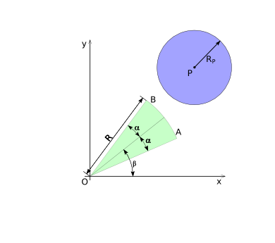
In order to determine if a circle-sector and a disk collide, we start with transforming the coordinates of the 2d space in such a way that the center of the circle-sector is located at the origin. The circle-sector can then be defined by a radius ''R'', a half-top-angle ''alpha'' and a placement angle ''beta'', as shown in diagram (1). | In order to determine if a circle-sector and a disk collide, we start with transforming the coordinates of the 2d space in such a way that the center of the circle-sector is located at the origin. The circle-sector can then be defined by a radius ''R'', a half-top-angle ''alpha'' and a placement angle ''beta'', as shown in diagram (1). | ||
The disk can simply be defined by its center-point ''P'' and its radius ''R<sub>P</sub>'', where point ''P'' can be anywhere in the 2d space. See diagram (1) for an overview. | The disk can simply be defined by its center-point ''P'' and its radius ''R<sub>P</sub>'', where point ''P'' can be anywhere in the 2d space. See diagram (CSD-1) for an overview. | ||
Diagram (1) | [[Image:Collision-circlesecor-disk-dimensions.png|frame|none|Diagram (CSD-1)]] | ||
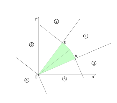
In order to determine if the circle-sector and the circle intersect, the x-y plane is divide in 6 ''Voronoi'' like regions. The regions are based on the vertexes ''O-A'', ''O-B'' and the arc ''A-B''. They are shown in diagram (2). | In order to determine if the circle-sector and the circle intersect, the x-y plane is divide in 6 ''Voronoi'' like regions. The regions are based on the vertexes ''O-A'', ''O-B'' and the arc ''A-B''. They are shown in diagram (CSD-2). | ||
Diagram (2) | [[Image:Collision-circlesecor-disk-voronoi.png|frame|none|Diagram (CSD-2)]] | ||
For each region it is now determined what the pre-conditions for an overlap are, if ''P'' is in that region. If necessary, the pre-conditions for point ''P'' being in the region will be derived as well. | For each region it is now determined what the pre-conditions for an overlap are, if ''P'' is in that region. If necessary, the pre-conditions for point ''P'' being in the region will be derived as well. | ||
| Line 25: | Line 25: | ||
=== Region 1 === | === Region 1 === | ||
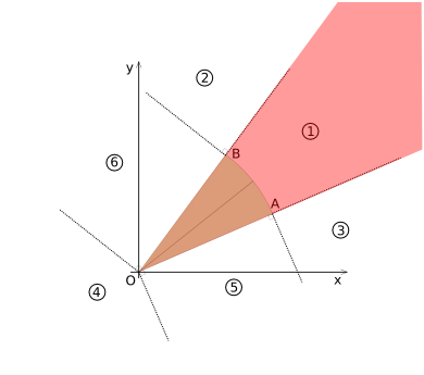
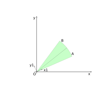
Region 1 is highlighted in diagram (3), it includes the interior of the Circle-sector. For region 1, the coordinates for point ''P'' are transformed to coordinate system 1 (shown in diagram (4)). | Region 1 is highlighted in diagram (CSD-3), it includes the interior of the Circle-sector. For region 1, the coordinates for point ''P'' are transformed to coordinate system 1 (shown in diagram (CSD-4)). | ||
Diagram(3) | [[Image:Collision-circlesecor-disk-voronoi1.png|frame|none|Diagram (CSD-3)]] | ||
[[Image:Collision-circlesecor-disk-axis1.png|frame|none|Diagram (CSD-4)]] | |||
The coordinates for point ''P'' in coordinate system 1 are: | The coordinates for point ''P'' in coordinate system 1 are: | ||
| Line 53: | Line 54: | ||
=== Region 2 === | === Region 2 === | ||
Region 2 is highlighted in diagram (5). For this region no coordinate transformations are necessary. | Region 2 is highlighted in diagram (CSD-5). For this region no coordinate transformations are necessary. | ||
Diagram (5) | [[Image:Collision-circlesecor-disk-voronoi2.png|frame|none|Diagram (CSD-5)]] | ||
If point ''P'' is inside region 2, the circle-sector and the disk can only intersect if point ''B'' is inside the circle. | If point ''P'' is inside region 2, the circle-sector and the disk can only intersect if point ''B'' is inside the circle. | ||
| Line 72: | Line 73: | ||
=== Region 3 === | === Region 3 === | ||
Region 3 is highlighted in diagram (6). For this region no coordinate transformations are necessary. | Region 3 is highlighted in diagram (CSD-6). For this region no coordinate transformations are necessary. | ||
Diagram (6) | [[Image:Collision-circlesecor-disk-voronoi3.png|frame|none|Diagram (CSD-6)]] | ||
Analogous to region 2, the circle-sector and the disk can only intersect if point ''A'' is inside the disk. The condition for this is: | Analogous to region 2, the circle-sector and the disk can only intersect if point ''A'' is inside the disk. The condition for this is: | ||
| Line 91: | Line 92: | ||
=== Region 4 === | === Region 4 === | ||
Region 4 is highlighted in diagram (7). For this region no coordinate transformations are necessary. | Region 4 is highlighted in diagram (CSD-7). For this region no coordinate transformations are necessary. | ||
Diagram (7) | [[Image:Collision-circlesecor-disk-voronoi4.png|frame|none|Diagram (CSD-7)]] | ||
Analogous to regions 2 and 3, the circle-sector and the disk can only intersect if point ''O'' is inside the disk. The condition for this is: | Analogous to regions 2 and 3, the circle-sector and the disk can only intersect if point ''O'' is inside the disk. The condition for this is: | ||
| Line 102: | Line 103: | ||
=== Region 5 === | === Region 5 === | ||
Region 5 is highlighted in diagram (8). For region 5, the coordinates for point ''P'' are transformed to coordinate system 2 (shown in diagram (9)). | Region 5 is highlighted in diagram (CSD-8). For region 5, the coordinates for point ''P'' are transformed to coordinate system 2 (shown in diagram (CSD-9)). | ||
[[Image:Collision-circlesecor-disk-voronoi5.png|frame|none|Diagram (CSD-8)]] | |||
[[Image:Collision-circlesecor-disk-axis2.png|frame|none|Diagram (CSD-9)]] | |||
In the local coordinates the following conditions for ''P'' being in region 5, can be formulated: | In the local coordinates the following conditions for ''P'' being in region 5, can be formulated: | ||
| Line 137: | Line 139: | ||
=== Region 6 === | === Region 6 === | ||
Region 6 is highlighted in diagram (10). For region 6, the coordinates for point ''P'' are transformed to coordinate system 3 (shown in diagram (11)). | Region 6 is highlighted in diagram (CSD-10). For region 6, the coordinates for point ''P'' are transformed to coordinate system 3 (shown in diagram (CSD-11)). | ||
[[Image:Collision-circlesecor-disk-voronoi6.png|frame|none|Diagram (CSD-10)]] | |||
[[Image:Collision-circlesecor-disk-axis3.png|frame|none|Diagram (CSD-11)]] | |||
In the local coordinates the following conditions for ''P'' being in region 6, can be formulated: | In the local coordinates the following conditions for ''P'' being in region 6, can be formulated: | ||
| Line 157: | Line 160: | ||
Now using the goniometric relations to seperate ''alpha'' and ''beta'': | Now using the goniometric relations to seperate ''alpha'' and ''beta'': | ||
:P<sub> | :P<sub>x3</sub> = P<sub>x</sub>{cos(alpha)cos(beta) - sin(alpha)sin(beta)} + P<sub>y</sub>{sin(alpha)cos(beta) + cos(alpha)sin(beta)} | ||
:P<sub> | :P<sub>y3</sub> = P<sub>y</sub>{cos(alpha)cos(beta) - sin(alpha)sin(beta)} - P<sub>x</sub>{sin(alpha)cos(beta) + cos(alpha)sin(beta)} | ||
The conditions can now be evaluated. | The conditions can now be evaluated. | ||
| Line 185: | Line 188: | ||
In the current combat implementation sin(beta) and cos(beta) do not need to be calculated at runtime. ''Beta'' is determined by the direction the attacker is facing. There are only four possible values for ''beta''; 0, pi/2, pi and pi*3/2. Because the half-top-angle is a property of the weapon used, sin(alpha) and cos(alpha) could be computed on startup of the game-server and stored for use. | In the current combat implementation sin(beta) and cos(beta) do not need to be calculated at runtime. ''Beta'' is determined by the direction the attacker is facing. There are only four possible values for ''beta''; 0, pi/2, pi and pi*3/2. Because the half-top-angle is a property of the weapon used, sin(alpha) and cos(alpha) could be computed on startup of the game-server and stored for use. | ||
''There is a trick for tan(2alpha), but I'm done for today.''[[User:Avaniel|Avaniel]] 05:43, 27 February 2007 (CET) | |||
Revision as of 04:43, 27 February 2007
This article is currently only a proposal
The features or design guidelines described in this article are only a proposal made by one or some persons. It has not been evaluated or accepted by the core development team yet. Feel free to add your personal opinion about them or make counter proposals.
This page was created to document the collision detection algorithms used in The Mana World. After the algorithms are converted to C++ and added to the code base it is very difficult to verify the assumptions and math of the author. Therefore an explanation of the algorithms used, is given below. Of course any improvements or clarifications can allso be added and discussed on this page.
Strictly speaking, the algorithms discussed here, compute if two geometric figures intersect. However, the result is then used in a dynamic game. In the game world two objects will collide if their movement areas intersect.
Circle-Sector with Disk
In order to determine if a circle-sector and a disk collide, we start with transforming the coordinates of the 2d space in such a way that the center of the circle-sector is located at the origin. The circle-sector can then be defined by a radius R, a half-top-angle alpha and a placement angle beta, as shown in diagram (1).
The disk can simply be defined by its center-point P and its radius RP, where point P can be anywhere in the 2d space. See diagram (CSD-1) for an overview.
In order to determine if the circle-sector and the circle intersect, the x-y plane is divide in 6 Voronoi like regions. The regions are based on the vertexes O-A, O-B and the arc A-B. They are shown in diagram (CSD-2).
For each region it is now determined what the pre-conditions for an overlap are, if P is in that region. If necessary, the pre-conditions for point P being in the region will be derived as well.
In the following text, a subscript x and y are used to indicate x and y coordinate of a point. If the coordinates considered are in a tranformed coordinate system, an extra indicator will be added. For example the x-coordinate of point A in the x1-y1 coordinate system is denoted as: Ax1
Region 1
Region 1 is highlighted in diagram (CSD-3), it includes the interior of the Circle-sector. For region 1, the coordinates for point P are transformed to coordinate system 1 (shown in diagram (CSD-4)).
The coordinates for point P in coordinate system 1 are:
- Px1 = Px cos(beta-alpha) + Py sin(beta-alpha)
- Py1 = Py cos(beta-alpha) - Px sin(beta-alpha)
Using goniometric relations this can be simplified to:
- Px1 = Px {cos(alpha)cos(beta) + sin(alpha)sin(beta)} + Py {-sin(alpha)cos(beta) + cos(alpha)sin(beta)}
- Py1 = Py {cos(alpha)cos(beta) + sin(alpha)sin(beta)} - Px {-sin(alpha)cos(beta) + cos(alpha)sin(beta)}
Point P is inside region 1 if
- Px1 >= 0 , Py1 >= 0 and Py1 <= Px1 tan(2alpha)
The Circle-sector and the disc then intersect if
- Px2 + Px2 <= (R + RP)2
Region 2
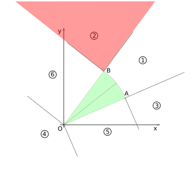
Region 2 is highlighted in diagram (CSD-5). For this region no coordinate transformations are necessary.
If point P is inside region 2, the circle-sector and the disk can only intersect if point B is inside the circle.
- (Px - Bx)2 + (Py - By)2 <= RP2
The coordinates of point B are:
- Bx = R cos(alpha + beta) = R {cos(alpha)cos(beta) - sin(alpha)sin(beta)}
- By = R sin(alpha + beta) = R {sin(alpha)cos(beta) + cos(alpha)sin(beta)}
With the coordinates for B the condition can now be evaluated.
Region 3
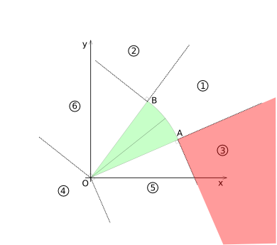
Region 3 is highlighted in diagram (CSD-6). For this region no coordinate transformations are necessary.
Analogous to region 2, the circle-sector and the disk can only intersect if point A is inside the disk. The condition for this is:
- (Px - Ax)2 + (Py - Ay)2 <= RP2
The coordinates of point A are:
- Ax = R cos(-alpha + beta) = R {cos(alpha)cos(beta) + sin(alpha)sin(beta)}
- Ay = R sin(-alpha + beta) = R {-sin(alpha)cos(beta) + cos(alpha)sin(beta)}
With the coordinates for A the condition can now be evaluated.
Region 4
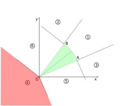
Region 4 is highlighted in diagram (CSD-7). For this region no coordinate transformations are necessary.
Analogous to regions 2 and 3, the circle-sector and the disk can only intersect if point O is inside the disk. The condition for this is:
- Px2 + Py2 <= RP2
Region 5
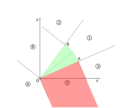
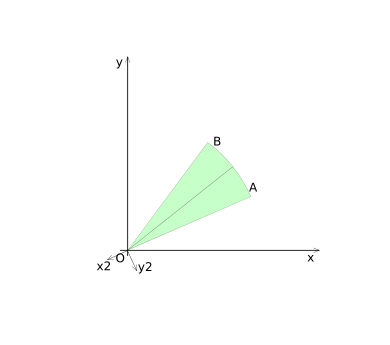
Region 5 is highlighted in diagram (CSD-8). For region 5, the coordinates for point P are transformed to coordinate system 2 (shown in diagram (CSD-9)).
In the local coordinates the following conditions for P being in region 5, can be formulated:
- Px2 <= 0, Px2 >= -R and Py2 >= 0
The condition for the circle-sector and the disk intersecting is:
- Py2 <= RP
The coordinates for P in coordinate system 2 are given by:
- Px2 = Pxcos(alpha + beta + pi) + Pysin(alpha + beta + pi)
- Py2 = Pycos(alpha + beta + pi) - Pxsin(alpha + beta + pi)
Using the goniometric relations to handle the pi term first, the coordinates become:
- Px2 = -Pxcos(alpha + beta) + Pysin(alpha + beta )
- Py2 = -Pycos(alpha + beta) - Pxsin(alpha + beta )
Now using the goniometric relations to seperate alpha and beta:
- Px2 = -Px{cos(alpha)cos(beta) - sin(alpha)sin(beta)} + Py{sin(alpha)cos(beta) + cos(alpha)sin(beta)}
- Py2 = -Py{cos(alpha)cos(beta) - sin(alpha)sin(beta)} - Px{sin(alpha)cos(beta) + cos(alpha)sin(beta)}
The conditions can now be evaluated.
Region 6
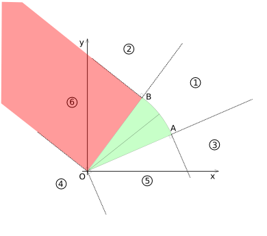
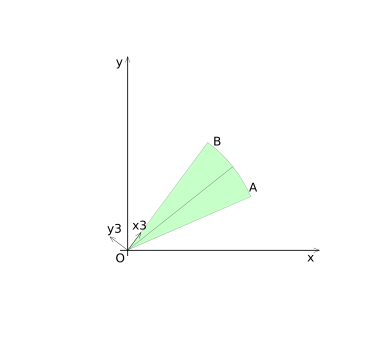
Region 6 is highlighted in diagram (CSD-10). For region 6, the coordinates for point P are transformed to coordinate system 3 (shown in diagram (CSD-11)).
In the local coordinates the following conditions for P being in region 6, can be formulated:
- Px3 >= 0, Px3 <= R and Py3 >= 0
The condition for the circle-sector and the disk intersecting is:
- Py3 <= RP
The coordinates for P in coordinate system 3 are given by:
- Px3 = Pxcos(alpha + beta) + Pysin(alpha + beta)
- Py3 = Pycos(alpha + beta) - Pxsin(alpha + beta)
Now using the goniometric relations to seperate alpha and beta:
- Px3 = Px{cos(alpha)cos(beta) - sin(alpha)sin(beta)} + Py{sin(alpha)cos(beta) + cos(alpha)sin(beta)}
- Py3 = Py{cos(alpha)cos(beta) - sin(alpha)sin(beta)} - Px{sin(alpha)cos(beta) + cos(alpha)sin(beta)}
The conditions can now be evaluated.
The Algorithm
The following values need to be given; the radius of the circle-sector "R", the half-top-angle "alpha", the placement angle beta, the coordinates of the center of the circle-sector, the coordinates of the center of the disk "P" and the radius of the disk "RP".
- Subtract the coordinates of the center of the circle sector from the coordinates of point P.
- Check for a region 4 intersection.
- Calculate sin(alpha), cos(alpha), sin(beta) and cos(beta) and store them in temporary variables.
- Calculate the coordinates of point A.
- Check for a region 3 intersection.
- Calculate the coordinates of point B.
- Check for a region 2 intersection.
- Calculate the coordinates of point "P" in coordinate system 2.
- Check for a region 5 intersection.
- Calculate the coordinates of point "P" in coordinate system 3.
- Check for a region 6 intersection.
- Calculate the coordinates of point "P" in coordinate system 1.
- Check for a region 1 intersection.
Any but the first three steps can be moved, if that is found to be more appropriate.
In the current combat implementation sin(beta) and cos(beta) do not need to be calculated at runtime. Beta is determined by the direction the attacker is facing. There are only four possible values for beta; 0, pi/2, pi and pi*3/2. Because the half-top-angle is a property of the weapon used, sin(alpha) and cos(alpha) could be computed on startup of the game-server and stored for use.
There is a trick for tan(2alpha), but I'm done for today.Avaniel 05:43, 27 February 2007 (CET)
